How Components Interact
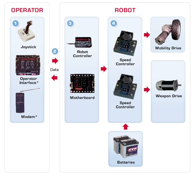
To get started, study this basic flow diagram illustrating the roles of a ‘bot’s most common components:

Four Required Components
These are the four components included in an IFI Isaac 16 System Bundle, which is required by BBIQ for safety reasons.
 |
An operator controls the robot via command signals generated by various types of control devices, such as a joystick. The operator control device plugs into the IFI "Operator Interface" (OI) which is plugged to the "Radio Modem" (RM) transceiver. |
 |
Data is sent from the RM to the "Radio Controller" (RC) through the air via radio waves. Helpful performance data is also sent back to the OI. |
 |
The "Motherboard" (MB) is the brains of the group. It translates the information/data from the RC and distributes the operator’s various commands to the appropriate component, such as a speed controller for mobility drive, a speed controller for a weapon, or a solenoid for pneumatics. |
 |
High amp discharge batteries are wired to the electronic speed controllers (ESC). The ESC receives full battery power but distributes to a component only the amount dictated by the operator, i.e. fast or slow, up or down, left or right. |